microwave amplifiers to 20ghz
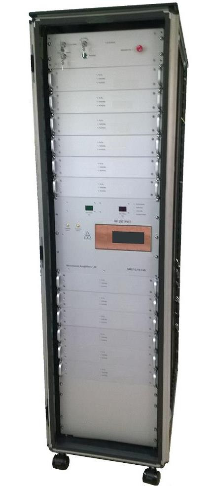
High-energy-physics - AM97/2.1GHz 14kW CW Tower System
The series AM97 covers frequencies of 2.08GHz to 2.12GHz and has a maximum output power of 14000 watts
14kW CW POWER . . . .
General Description
The AM97 is a Class AB LDMOS power amplifier system, intended for applications in high-energy physics. The latest LDMOS semiconductor devices offer high efficiency and reliability, reducing heat dissipation and power consumption so extending product life. The amplifier is suitable for use with CW signals, or with pulsed signals using a fast blanking TTL command line to switch transistor bias levels so that the amplifier will be in a class AB state for the duration of an RF pulse, but otherwise in a standby state. The design is modular and upgradeable, and designed for on-site maintenance by exchanging shelves, thereby minimising down-time. Forced air cooled and water-cooled versions are available.
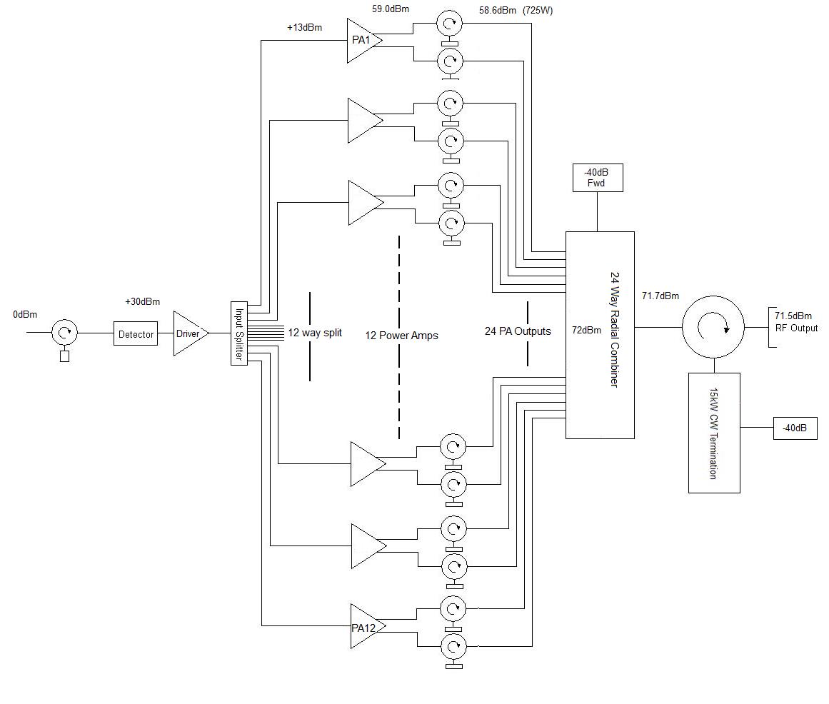
Simplified RF Schematic
System Configurations
This system described here is fully loaded, although systems can be configured containing any number of PA shelves according to the output power requirements, with the ancillary components arranged as necessary. Provision can be made for future upgrades, or system components upgraded universally. PA shelves are standard AM97 series items and can be used in future upgrades or interchanged between systems. Other system components are upgradeable subject to modification, or can be supplied with an inbuilt capacity for future upgrades.
Electrical:
Frequency Range 2100MHz +/-20MHz)
Output Power (Psat) 14kW (Note 1)
Output Power Variation Vs Frequency 0.25dB p-p max
Power Gain 70dB min
Maximum Continuous CW RF Input +13dBm
Absolute Maximum CW RF Input +20dBm
RF Input Signal CW or Pulsed
Duty 100%
RF Rise & Fall Time 200nS max, 50nS typ (Note 2)
Harmonics @ P1dB -45dBc (2nd) -60dB (3rd)
Non-Harmonic Spurious Output -60dBc min
Input to Output Isolation 80dB min (Note 3)
Input Return Loss 17dB min, 20dB typ
Output Return Loss 25dB min (1.1:1 VSWR)
Forward Power Sample -43 dBc nom.
Reflected Power Sample -43 dBc nom.
Max Load VSWR Infinite (survival) Note 4
Reflected Power Warning Psat -10dB (Note 4)
TTL PA Enable Transition Time 5uS min (Note 5)
TTL PA Enable Signal HIGH = amplifier bias ON (Note 6)
System Efficiency @ Peak O/P 40% nom
RF PA AC Power Supply 110V AC 50/60Hz
RF PA DC Power Supply See sect 3.3.3
Notes:
- Saturation, where an increase in RF drive does not increase the RF output
- The RF rise/fall times are quoted with the amplifier enabled
- RF leakage at output port with input applied amplifier biased off
- This system will not be damaged by operation into severe mismatch, and will continue to operate. The system is fitted with a water-cooled output isolator in waveguide with a dummy load to absorb reflected power. PA shelves are fitted with circulators & dummy loads to provide instantaneous protection from full power mismatch, and reflected power detectors which activate a shut-down of the shelf in case of the failure of the system dummy load. A reverse power alarm is provided for customer monitoring of reflected power. This protection system prevents the catastrophic damage that high levels of reflected power may otherwise cause.
- This is the period of transition between standby & active states. During the standby state the amplifier is disabled drawing minimal power, and cannot amplify an RF signal. In response to a TTL (high) command, the amplifier switches to an active state and is able to amplify a pulse. The duration of this transition is the Enable Rise Time. When reverted to the standby state, the duration of the transition is the Enable Fall Time. Note that the application of RF signals during these transitions will result in a distorted output.
- The TTL control signals required are not true TTL. The amplifier assumes “LOW” when not connected. HIGH - Logic 1 = >3.2V, LOW - Logic 0 = <1.2V
Mechanical: 19” Rack Full Height
Dimensions (LWH) 19” x 2000 x 1050mm (42U)
Weight 450Kg nom (full system)
Input & Control Shelf 3U
PA Shelf 2U
Output Combiner Panel 8U
DC Distribution 4U
Water Cooling Inlet Panel 3U
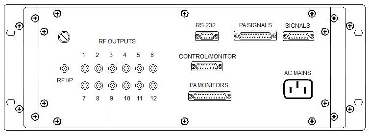
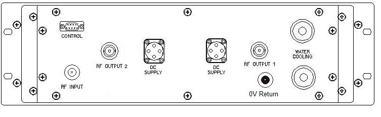
Connectors:
RF Input Rear panel SMA female
RF Output Waveguide WR430
FWD Power Sample SMA Female
REV Power Sample SMA Female
Control/Monitor 15-Way D-type socket
RS232 9-Way D-type socket
Environmental Specifications:
Operating temperature range 5C min to 40C ambient
Storage temperature range 5C to +75C
Humidity 95% non-condensing
On no account must the amplifier be exposed to water ingress, other than that used in the cooling system. The amplifier must not be subjected to temperatures below 0C if filled with coolant, which may result in catastrophic damage to the cooling system. The system must be drained, and blown through with compressed air if transportation or storage below 0C is required. Note that the coolant connections have shut-off valves which retain the coolant when disconnected.
Front Panel Controls:
AC power keyswitch Activates RF PA AC power supply
DC power keyswitch Activates remote AC-DC Power Supply (DC ON, Bias OFF)
Emergency OFF pushswitch Deactivates remote AC-DC PSU. LED illuminated RED
Remote/Local keyswitch Selects Local or Remote operating mode
PA Enable Pushswitch Sets amplifier into Bias ON condition
Rear Panel Controls:
TTL PA Enable Enable/Disable (TTL High = Bias ON)
Front Indicators:
Forward RF Power Display Illuminated Green 3.5 digital forward power meter calibrated in kW
Reverse RF Power Display Illuminated Red 3.5 digital forward power meter calibrated in kW
AC power indicator Red LED indicates AC power to RF PA is ON
RF input status indicator Red LED indicates RF input > -10dBm nom
RF output status indicator Red LED indicates system RF output > 1kW nom
PA RF status indicators Red LEDs indicates PA shelf RF output > nominal 100W
PA DC status indicators Red LEDs indicate presence of DC at PA shelf
Over temp indicators White LEDs indicate over temp shut-down of each PA shelf
VSWR indicator White LED indicates excess reflected power
Coolant flow indicator &shut-down White LED indicates low coolant flow shutdown
Emergency/Interlock White LED indicates interlock status (ON = shutdown)
Monitor Signals:
DC status monitor TTL high = DC at DC power outlets of PSU Unit
RF status monitor TTL high = RF output >nominal 1000W
PA RF status monitors TTL high = PA shelf RF output > nominal 100W
Over Temp monitors TTL high = PA shelf over temp shut-down
Coolant flow TTL hign = low coolant flow and shutdown
Reflected power TTL High= High reverse power alarm
Emergency/Interlock TTL high = Shut-down (Local or Remote).
DC Detector output +5V nom @ max rated RF output (dynamic range >10dB)
Safety Interlocks:
A pair of NO contacts are located at the at the Control/Monitor connector which must be made for the system to operate. A jumper is factory fitted as delivered.
Removal of any shelves or opening of the rear door will activate the safety interlock and shut the system down.
It is necessary to perform a system reset to restore operation in the event of shut-down.
Emergency OFF:
An Emergency OFF shutdown can be performed at the Local control location, regardless of which mode (Local/Remote) the amplifier is being operated in by pressing the RED push-switch. In the event of such shutdown, a system reset is required for subsequent operation
RS232 Interface:
The RS232 interface operates in parallel with the TTL control lines without any precedence. TTL or RS232 commands may be used to control the amplifier. A TTL disable command will NOT disable the system if it is enabled by RS232 and vice-versa
PA Enable/Disable (controls DC bias supply to RFPA)
Local Override
DC status monitor DC at DC power Outlet of PSU
RF status monitor RF output >nominal 1000W
PA RF status monitor PA shelf RF output > nominal 100W
Over Temp monitor PA shelf over temp shut-down
Coolant flow low coolant flow shut-down
Reflected power monitor High reverse power
Emergency/Interlock Safety shut-down (local or remote).
Forward RF output Forward RF power (dynamic range >10dB)
Reverse RF output Reverse RF power (dynamic range >10dB)
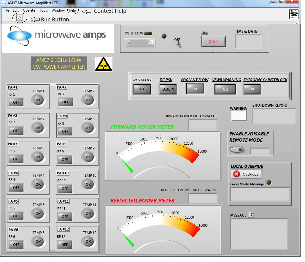
GRAPHIC USER INTERFACE (GUI)
The GUI allows control and monitoring of the AM97 Amplifier via RS232 interface.
System Components:
The system is a modular design. PA modules may be withdrawn from the chassis and replaced with the minimum of electrical and mechanical disassembly.
Input & Control Shelf:
The RF input is split into signals of equal amplitude and phase within this shelf, to provide inputs to the PA shelves. The input signal is detected and converted to DC providing RF input monitor signals. This shelf also contains system control and monitoring electronics, and AC-DC power supply.
Gain/Power adjustment is possible using the control knob immediately above the RF Input port. The maximum power is achieved with the adjustment turned fully anti-clockwise. Factory set for 14kW output power with +1dBm RF drive. Note that this control is intended for commissioning only and not for user adjustment.
Power Amplifier Shelf:
The system contains twelve 1.5kW AM96 RF power amplifiers. Each PA contains a single power module of corporate structure design, using eight power transistors to provide two phase matched outputs of 725W each. This allows the use of derated power combiners and circulators for reliability overhead. The failure of a single device in a PA shelf will not have a significant effect on the system output power. PA shelves are fitted with circulators & dummy loads to provide instantaneous protection from full power mismatch, and reflected power detectors which activate a shut-down of the shelf under excessive mismatch conditions. The temperature of the PA is monitored and a shut-down activates in the case of overheating. The shelves are located on fixed supports within the rack, and removed with disconnection of the electrical & mechanical connections at the rear, and the front panel securing screws.
DC Power Supply Unit:
The amplifier requires a power supply of +32V DC, with a rating of at least 50kW. An additional overhead may be required depending on long cable-run losses.The PSU supplied with the equipment is model AMP32-50K. This is a modular design housed in a 19” rack/chassis of 20U height. Please see product specification AMP-06-001.
Output Combiner:
The outputs from the PA’s are combined using a 24 way radial power combiner. Failure of a PA shelf output will result in an approximately proportional reduction in the output power of the system. The final combiner includes a forward directional coupler providing the RF signal to drive the forward detector module (meter driver) located within the shelf, and to provide a forward RF sample. Fitted to the combiner is the water-cooled output circulator with dummy load rated to absorb the full 14kW reflected power. A reverse power detector is also included in the dummy load to drive the reflected detector module, and to provide are reflected RF sample. It also activates a warning system in the event of excessive reflected power.
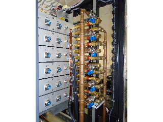
Cooling System
The PA modules are fitted with water-cooled heatsinks which maintain the modules below their maximum permitted case temperature. The heatsinks are fabricated in aluminium, with pressed-in copper coolant carrying pipework. Connection to the rear panel mounted inlet is in copper pipe. Three inlets and three outlets are provided which must all be connected prior to operation.
The output isolator assembly is fabricated in aluminium, internally plated with copper on electroless nickel. Coolant is not in contact with any aluminium. Coolant flow in the system is monitored with an alarm activating if the flow level in any circuit is too low, and a system shutdown.
Water supply : Demineralised water is recommended to prevent calcification
Inlet water temperature : 20-30C
Water pressure : 8bar max
Flow rate : 20L/min @ coolant temp 20C, 40L/min @ 30C each cooling cct
Connections : ½” male self-sealing with Swagelok Quick-connect SS-QC8-B-8MT coupling
Maintenance
Periodic maintenance is required, limited to verification of the status indicators and visual examination. Shelves may be removed and exchanged for service, however there are no user-serviceable parts. Each system is factory tested and supplied with a set of test results. If degradation in performance to below the specified levels occurs or a failure is suspected, details should be reported to the manufacturer for diagnostic evaluation. A maintenance & operation manual is supplied with the equipment. The user may determine from the system status indication if a problem exists within a particular shelf. That shelf alone may then be returned to the factory for investigation.
Warranty
Microwave Amplifiers Ltd warrants for 2 years from date of shipment that the goods supplied will be in full compliance with the agreed specifications and will be free from defects in material and workmanship. Any and all other warranties (except of title) express or implied, relating to fitness for particular purpose, merchantable quality or otherwise are expressly disclaimed. Seller will not be responsible for special or consequential loss or damages. Liability shall be limited to the repair or replacement of defective products subject to the return of the product intact, and un-tampered with by the buyer.
Microwave Amps Ltd,
103 South Liberty Lane
, Bristol
, BS3 2SZ
T: +44 01275 853196
E: sales@maltd.com
