microwave amplifiers to 20ghz
High-energy-physics - AM61/X-Band-(11.4GHz & 12GHz) -1200W
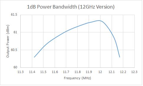
The series AM61 covers frequencies of 11.40GHz to 12.00GHz and has a maximum output power of 1300 watts

11.4GHz & 12GHz 1200W GaN Amplifiers:
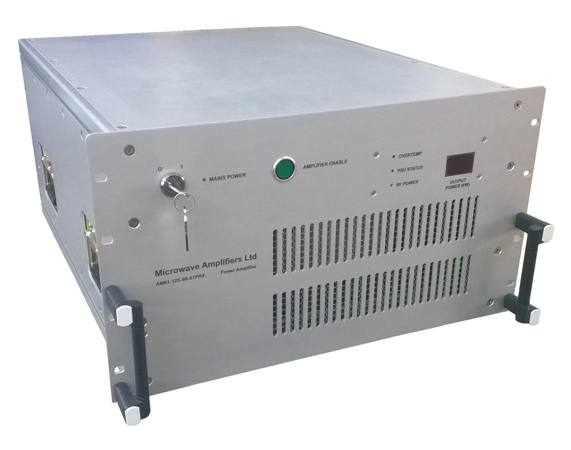
Utilising the latest GaN power transistor technology, the AM61 X-band amplifiers are designed for high efficiency pulsed power. With fast rise times & low pulse distortion the amplifier is ideally suited to applications in high-energy physics, typically as drivers for Klystron tubes. Four of our 400W units are combined using a waveguide stucture minimising losses and maintaining a tight phase balance, whilst ultra stable power supply technology gives a low jitter output response. Remote control is provided either by conventional TTL, or using RS232 based Graphic User Interface (GUI), whilst power and status monitoring may be provided by the GUI or as RF/analog outputs. Protection circuits are incorporated to ensure safety and long-term reliability. The amplifier is housed in a rugged 19" rack mountable chassis only 6U in height.
The amplifier is operated in a Gated mode, with the RF transistor bias controlled by a TTL command synchronised with the RF pulse. The transistors are in a biassed state only during the RF pulse, and otherwise in standby. This design provides for high power outputs but without the disadvantages of high power consumption and heat generation, and with the amplitude variation and phase excursions caused by transistor junction heating being reduced by the application of pre-pulse bias.
Specifications
- Centre Frequency : 11.4GHz & 12GHz options
- Peak Output Power : 1200W min, 1400W typ @ 1% duty (note 1)
- Small Signal Gain : 66dB min, 70dB typ
- Input Power for Rated Output : -5dBm nom
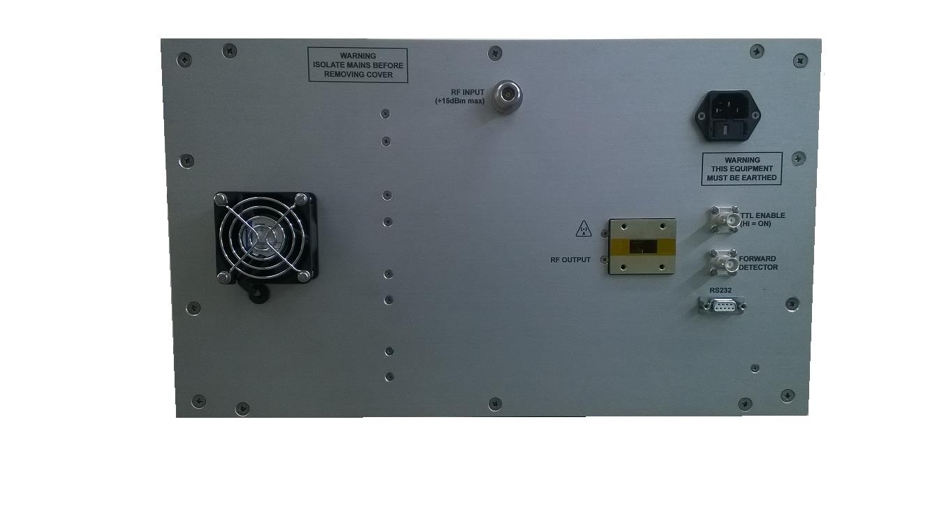
- Absolute max input Power : +15dBm (CW)
- Duty Cycle : 1% max
- Input Signal Characteristic : Pulsed
- Input Pulse Width : 100uS max
- Pulse Repetition Frequency : 5KHz max
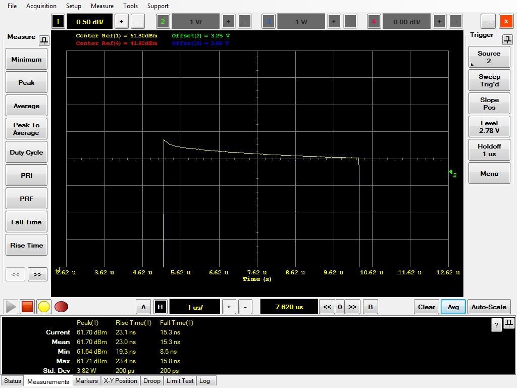
- Pulse Droop 0.3dB typ in 5uS pulse, 1dB typ in 100uS max @ peak O/P
- RMS Amplitude Stability : 0.02% typ
- RMS Phase Stability : 0.036deg typ
- RF Drive for Optimum Stability : -5 to 0dBm
- Harmonics: -40dBc max
- Non Harmonic Spurious Output : >80dBc
- Input Return Loss : 14dB min
- Output Return Loss : 18dB min
- System Power Supply : Mains AC230V 1-phase
- Gate ON Time : 5uS max. 2uS typ (note 2)
- Gate OFF Time : 2uS max, 0.5uS typ
- Pulse control fall time (100-0% RF) : 5uS max
- RF Rise/Fall time : <20nS nom
- TTL Gating Signal : TTL HIGH = amplifier biassed ON
- TTL Enable Signal (remote control) : TTL HIGH = amplifier ACTIVE
Notes
1. Duty Cycle The amplifier duty cycle is limited to 1% at which the amplifier may be continuously operated. The pulse width and repetition frequency of the RF signal may be varied as required within the stated limits, but must not exceed the maximum rated duty. Full performance is specified at the nominal duty conditions. Built-in protection against excessive duty cycle in incorporated, which will automatically limit the RF output if this level is exceeded.
Typical Pulse shape 5uS
2. Gating ON/OFF time: This is the period of transition between standby & active states. During the standby state the amplifier is disabled drawing minimal power, and can not amplify an RF signal. In response to a TTL (high) command, the amplifier switches to an active state with full DC bias, and is able to amplify a pulse. The duration of this transition is the Pulse Control Rise Time. At the end of the pulse the amplifier may be reverted to the standby state. The duration of this transition is the Pulse Control Fall Time. Note that the application of RF signals during these transitions will result in a distorted output. The TTL control line is AC coupled to prevent accidental use of CW RF input signals.
Signal Interfaces
- RF Input : N type female panel jack
- RF Output : Waveguide 17
- Signals: D-type
Mechanical
- Dimensions (LWH): 19” x 6U x 550mm. Rack or bench top style chassis
- Weight: 40Kg nominal
The front panel mountings should not be used to support the entire weight of the amplifier when mounted in a 19" rack. The side extrusions accept M5 captive nuts, which should be located at the rear of the unit to provide additional support. Alternatively, the amplifier should be rested on a tray within the rack.
Front Panel Controls & Indicators
- Main power keyswitch Initialises unit & activates cooling system.
- Amplifier Enable switch Illuminated push switch turns RF amplifier module on.
- PSU status indicator displays status of AC/DC convertors.
- RF status indicator shows presence of RF at output port
- TTL status indicator shows presence of TTL-high enable signal
- Over temperature indicator shows amplifier shut-down due to over temp.
- Output Power Meter Digital LED meter reading peak forward output power in watts (Limited accuracy where prf <10Hz or PW <1uS)
Output power limiter Amplifier output is limited if average RF output power exceeds 2% duty.
Reverse Power Protection Integral output isolator provides full power mismatch protection.
Over temperature protection Monitors power module temperature, with automatic over temp shut-down (with front panel indication) and auto reset.
Environmental
- Operating temperature range: 0 to 40C ambient
- Storage temperature range: -20 to 85C
The amplifier should be operated in a clean environment. Operation in sand/grit/dust environment may severely reduce the life of the internal cooling fans. The front (intake) and read (exhaust) of the amplifier should not be obstructed. On no account must the amplifier be subjected to water ingress.
Operation
An RF signal may be amplified only when a TTL command is applied at the pulse control connector. Full details of the operating procedure are detailed in the operating manual supplied with the equipment.
Amplifying a Pulsed RF Signal: It is necessary to synchronise the RF pulse with the TTL pulse control signal. This is accomplished using two square wave pulse generators capable of the desired PRF, one as master the other as slave. The slave is configured to trigger a pulse from an RF source, the master to output the TTL pulse control signal to the amplifier and after the required delay (pulse control rise time), trigger the slave.
NB. It is not necessary to program a delay between the end of the RF pulse and the TTL pulse control signal.
-400W-rf-amplifer-11.38GHz-to-11.42GHz-frequency-400-watts-output-power_typical-pulse-timing.jpg "Typical pulse timing for 10uS RF pulse")
Deliverables Each amplifier is supplied packed in a purpose designed carton containing:
- Pair of keys for front panel keyswitch. These are uncoded and factory replaceable.
- Pair of front panel handles with fixing screws. These are removed for transit.
- Mains power cable 2m.
- Operating manual with test data.
- Flashdrive with GUI drivers
Maintenance
No maintenance is required in normal operation and there are no user-serviceable parts within the amplifier. Each amplifier is factory tested and supplied with a set of test results. If degradation in performance to below the specified levels occurs, or a failure is suspected, then the complete unit should be returned to the manufacturer together with details of the fault.
Safety
The amplifier is subject of safety tests at the factory is supplied compliant with the LV and EMC Directives and bears the CE marking. The amplifier is heavy and care should be taken when lifting. Carrying handles are provided at the front panel. Hazardous voltages are present within this line-operated unit. Do not remove any panels. The centre conductor of the RF output connector should not be touched whilst the unit is in operation. Up to 1200W RF power can be present which may cause skin burns. Connection to the RF output port must not be made or broken whilst operating at high power levels. This may result in damage to or destruction of the output connector. The amplifier MUST be grounded. Line supply is filtered within the amplifier. A slow-blow fuse is located in the mains inlet. Should this repeatedly fail the amplifier should be returned to the factory for investigation. Small objects and thin cables etc should be kept away from the rear panel cooling fans which are fitted with finger guards.
Warranty
Microwave Amplifiers Ltd warrants for two years from date of shipment that the goods supplied will be in fully compliance with the agreed specifications and will be free from defects in material and workmanship. Any and all other warranties (except of title) express or implied, relating to fitness for particular purpose, merchantable quality or otherwise are expressly disclaimed. Seller will not be responsible for special or consequential loss or damages. Liability shall be limited to the repair or replacement of defective products subject to the return of the product intact, and un-tampered with by the buyer.
Microwave Amps Ltd,
103 South Liberty Lane
, Bristol
, BS3 2SZ
T: +44 01275 853196
E: sales@maltd.com
